A wiring diagram is an easy visual representation from the physical connections and physical layout associated with an electrical system or circuit. What can be a wiring diagram.

How To Wire A 3 Way Light Switch Family Handyman

How Electrical Receptacles Work

3 Prong Power Cord With Open Wiring 6 Ft
This multi function vehicle end connector converts any 4 way flat vehicle end plug to a combination 7 way outlet and 4 pole flat outlet.

Wiring diagram for standard outlet. What is a wiring diagram. A schematic shows the plan and function for an electrical circuit but is not concerned with the physical layout of the wires. A wiring diagram is a simple visual representation from the physical connections and physical layout associated with an electrical system or circuit. Standard wall outletreceptacle wiring. Electrical wiring is an electrical installation of cabling and associated devices such as switches distribution boards sockets and light fittings in a structure. The diagram above shows the power entering into the circuit at the switch box location then sending one power line for the dishwasher and a switched leg for the garbage disposal. This diagram illustrates the wiring for multiple ground fault circuit interrupter receptacles with an unprotected duplex receptacle at the end of the circuit. How is a wiring diagram different from a schematic. Gfci receptacle in a series with an unprotected outlet. Whether you are considering a backup power system want to add another electric circuit or are going to install a new appliance it is important to understand the homes electrical wiring basics and applicable codes. Adapts 4 way flat to both 7 way round and 4 way flat includes integrated test lamps which display proper connections shows if the wiring on your trailer isnt working properly burned. The diagram below shows the power entering the circuit at the grounded outlet box location then sending power up to the switch and a switched leg back down to the outlet. When wiring a wall outlet the neutral white wire should connect to the white or silver metal screw. These electrical wiring diagrams show typical connections. These wiring diagrams show typical connections.
Rough Electrical Wiring

How To Wire A Split Receptacle

Plug Schematic Wiring Diagram

Gfci Wire Diagram Wiring Diagram

Electrical Plug Wiring For A House Wiring Diagram Box

Rj11 Wiring Pinout Wiring Diagram

Ac Wiring Diagram Symbols Chart Full Size Of Automotive Wiring

Wrg 5951 Wiring Gfci Receptacles In Series

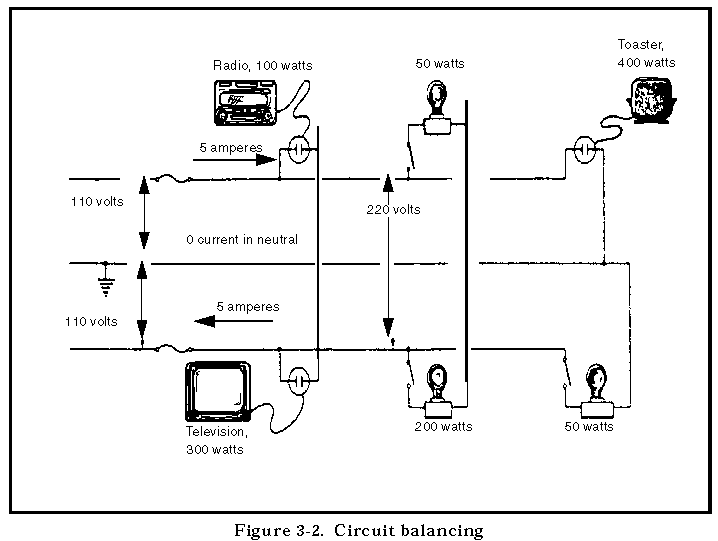
Fm 5 424 Theater Of Operations Electrical Systems Design And Layout

How To Wire Multiple Outlet In Parallel Electrical Wiring Diagram

Rv 50 Amp Wiring Wiring Diagram Pro

50 Amp Rv Schematic Wiring Diagram Wiring Diagram Data Schema

How To Wire A Split Receptacle

Amp 2v Outlet China Wall At Standard 20 220v Gfci Style Outlets

Electric Dryer Plug Types 3 Prong Outlet Home Depot 4 Wire Wiring