Less common symbols are explained where they occur. 3 wire connection diagram c electronic p1 p2 a1 p3 p4 module p5 a2 control voltage n p p coil n voltage 3 3 p1 p2 p3 p4 p5 electronic module c a2 a1 c fuse 2 fuse coil voltage 2 off g on r cc p n off on p1 p2 p3 p4 p5 a1 c fuse coil voltage 2 cc p hand off auto table b.

Submarine Electrical Systems Chapter 3

Run Stop Relay Circuit

5 Contactor Circuits
You must watch this video.

Wiring diagram to hold contactor. Make sure that the contacts of the contactor are rated in both voltage and current to handle the expected load that will be required by the equipment being powered. I have fallen at the first hurdle and am having problems wiring a contactor up to a switch which will then control 2 lights. Contactors are available from building and construction supply stores as well as some larger hardware storesstep 2 study the contactor manufacturer information. Step 1 acquire the contactor. 2 days ago i wired 380 to 440 volts contactor for a 3 phase motor and save these. Optional wiring and pilot devices for mechanically held contactor 2 wire control off on off auto selector switch. How to wire a contactor and motor protection switch. How to wire a contactor and overload. Im back at college and have been let loose on some wiring problems. The may be 2 or more sets of output contacts. Note the symbols used in this publication were adapted by allen bradley for use in accordance. A simple circuit diagram either of the two start buttons will close the contactor either of the stop buttons will open the contactor. Contactor wiring and i hope after this post you will be able to wire a 3 phase motor i also published a post about 3 phase motor wiring with magnetic contactor and thermal overload relay but today post and contactor wiring diagram is too simple and easy to learn. Wiring diagram book a1 15 b1 b2 16 18 b3 a2 b1 b3 15 supply voltage 16 18 l m h 2 levels b2 l1 f u 1 460 v f u 2 l2 l3 gnd h1 h3 h2 h4 f u 3 x1a f u 4 f u 5 x2a r. Use transformer if you need to.
The manufacturer information will identify the 2 input pins for 120 volts ac control. Symbols common to most circuits are explained on page 5. This book contains examples of control circuits motor starting switches and wiring diagrams for ac manual starters drum switches starters contactors relays limit switches and lighting contactors. Dol motor starter with 230v contactor coil. The control station wiring diagram is a representation of the physical station showing the relative positions of units the suggested internal wiring and connections with the starter.

How Does A Contactor Work What Is A Contactor Contactor Wiring

Wiring Contactors Diagram Shelectrik Com
Electrical Relay And Solid State Relays For Switchingbasic

3 Phase Stop Start Switch Electricians Forum Talk Electrician

Motor Control Fundamentals Wiki Odesie By Tech Transfer
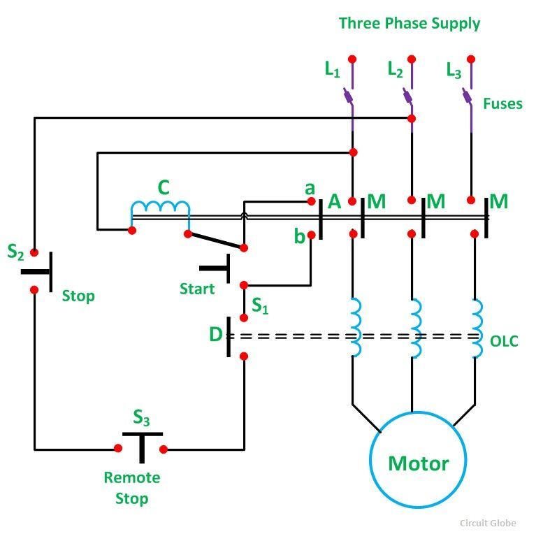
What Is Direct On Line Starter Its Theory Of Starting Circuit Globe

How To Wire A Relay

Contactor Wire Diagram Diagram Data Schema

Three Phase Induction Motor Starting Methodology Assessment Power

Direct Online Starter Dol Starter Diagram Full Explained Etechnog
Medium Voltage Contactor 800 A 2400 7200v Series F

Motor Control Circuits Ladder Logic Electronics Textbook

Controlling Motor Starting Wiki Odesie By Tech Transfer

Direct On Line Starter क य ह 3 Phase Dol Starter

116 Best Electrical Residental Images In 2019 Electrical Work


