Open loop and closed loop. The can bus is a common digital network used in automotive industrial medical and scientific systems for routing sensor data between pieces of equipment.

Building Simple Resistor Circuits Series And Parallel Circuits

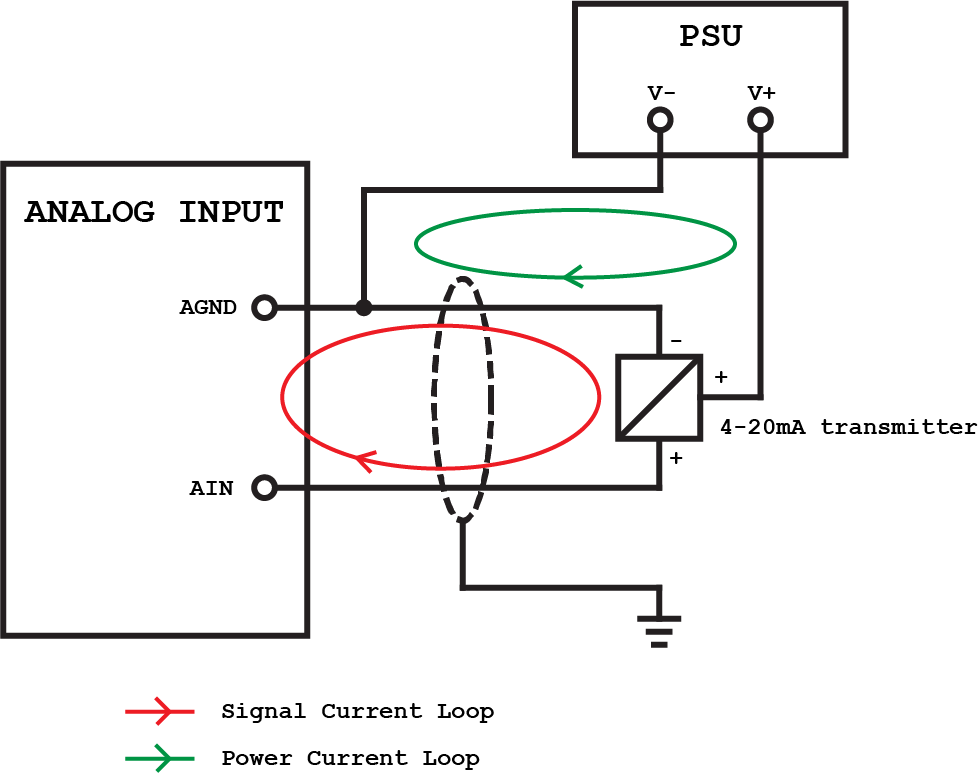
Current Loop Connection Divize Industrial Automation

Dali For Electricians Zencontrol
In an open loop control system the control action from the controller is independent of the process variable.

Loop wiring diagram examples. Can bus wiring diagram a basics tutorial. Open loop and closed loop control. The sparkfun inventors kit sik is your map for navigating the waters of beginning embedded electronics. Wiring is an electronic sketchbook and hardware electronics for developing ideas. Image developed using fritzing. I have included a wiring diagram a tutorial on how to set the current limit and many example codes. For loop iteration parallelism is a feature introduced in labview 2009 that executes the iterations of a for loop concurrently in multiple threads yielding greater cpu utilization and reduced processing time on multicore machines. In addition the terminal blinks in the context help window and on the icon to help you verify that you are wiring to the correct terminal. This guide contains all the information you will need to build five projects encompassing the 16 circuits of the sik. This article includes everything you need to know about controlling a stepper motor with the a4988 stepper motor driver and arduino. There are several sections in this website that you should read regarding track wiring. When you pass the wiring tool over a terminal a tip strip appears with the name of the terminal. This section part ii covers track wiring. It is a context for learning fundamentals of computer programming and prototyping with electronics within the context of the electronic arts. In australia where the loop is oriented vertically the wires could all be routed underneath.
There are two common classes of control action. Recent examples on the web. Connect three wires to the board. The first two red and black connect to the two long vertical rows on the side of the breadboard to provide access to the 5 volt supply and ground. For more circuit examples see the fritzing project page. The loop requires rerouting the plugs internal wiring.

Circuit Diagram Explained Wiring Diagram

Back To Basics The Fundamentals Of Loop Powered Devices Precision
Safety Circuit Examples Of Safety Components Technical Guide
How To Read A Schematic Learn Sparkfun Com

Ez Wiring Diagram Best Of Painless Wiring Diagram Examples Pictures
All About Plc Analog Input And Output Programming

Control Loop Wiring Diagram Wiring Diagram Data Schema

Light Switch Wiring Diagrams Do It Yourself Help Com

Light Switch Wiring Diagrams Do It Yourself Help Com

Current Loop Connection Divize Industrial Automation

Building Simple Resistor Circuits Series And Parallel Circuits

Chapter 2 Traffic Detector Handbook Third Edition Volume I Fhwa

Current Loop Connection Divize Industrial Automation

Open Loop System And Open Loop Control Systemsbasic Electronics

Light Switch Wiring Diagrams Do It Yourself Help Com


