In this video you will learn how to convert a basic wiring diagram to a ladder logic plc program. A wiring diagram is a sort of schematic which uses abstract pictorial symbols to show all the interconnections of elements in a system.

Dtam Cable Cross Reference Wiring Diagrams Manualzz Com

Electrical Schematic Design Software Zuken En

Delta Plc To Hmi Communication Cable Pinout My Plc Diary
Plc wiring 35 in the example there are two inputs one is a normally open push button and the second is a temperature switch or thermal relay.

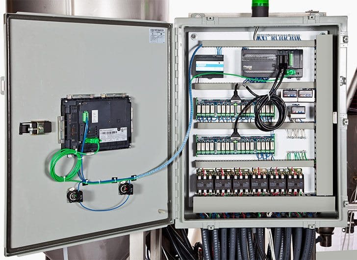
Plc cable wiring diagram. Electrical wiring diagrams of a plc panel in an industrial setting a plc is not simply plugged into a wall socket. D2 250 to d2 240 communications wiring using rs 232. Remove and lock out input power from the controller and io before any plc installation and wiring begins. We have used lt plc lx series in this tutorial with. D2 250 to d2 250 communications wiring using rs 232 or rs 422. Wiring diagrams and specifications. The electrical design for each machine must include at least the following components. Plc wiring diagram software just whats wiring diagram. Automation systems can fail and may result in. A cater 1 ettn tarted safety guidelines warning. One of the many advantages to using a plcpac is the simplicity of the io wiring. Providing a safe operating environment for personnel and equipment is your responsibility and should be your primary goal during system planning and installation. Io devices are wired to io points on a fixed io unit and to io modules in a modular unit. Check module type and model number by inspection and on the io wiring diagram. This can be a very handy skill to learn especially if you are converting a machine to plc control.
22 dl105 plc user manual 3rd ed. 230 glossary of specification terms. Verify that all modules are in the correct slots. In this tutorial video we explain about basics of plc wirings. Pc to mitsubishi sc 02nsc 05 adapter cable if more than one serial port is necessary on an a series melsec plc the aj71c24 or aj71c21 serial communication modules can be plugged into the system. Its covers wiring the plc power up termnials input wiring and output wiring. The serial cable layout to connect this converter to a pc is shown in this diagram. D0 cbl rs 232 rj12 to rj12 shielded cable wiring diagram.

Omron Plc To Rs 232 Calbe Pinout Diagram Pinoutguide Com

Micrlogix Plc Cable Wiring Diagram Wiring Diagram And Schematics

Compact Plc Library Kontek Eng

Rs232 Lg Plc Cables Pinout Cable And Connector Diagrams Usb

Programmable Controllers Technical Guide Australia Omron Ia

1072621 Wiring 1492 Cablexxxtbch Digital Io Ready Cable To 1756

Modbus Plus Wiring New Viddyup Com

Omron Plc Wiring Diagram Wiring Diagram Data Schema

Wiring Diagram Plc Wiring Diagrams

Omron Plc Cable Diagrams
Basic Electrical Design Of A Plc Panel Wiring Diagrams Eep

How To Make An Ethernet Cable The Ultimate Guide
Mitsubishi Plc Cable Diagrams

Delta Dvp Plc Communication Cable Wiring Diagram
P5series


